
COMPUTER AIDED DESIGN
GOALS FOR THE WEEK
- Evaluate and select 2D and 3D software
- Demonstrate and describe processes used in modelling with 2D and 3D software
2D CAD
RASTER Vs VECTOR
Both Vectors and Rasters are made of pixels. Vector graphics have anchor points and they are connected by formulas
and can change shape according to the connections. Both look the same when scaled down.
Raster Graphics have a limited
amount of pixels and gets blurry when scaled, Raster graphics are large files, has millions of elements and
increases the size on scaling up, Raster graphics are used for detailed images like photos.
Vector Graphics are recreated mathematically and the scaling will not affect their quality, Vector files are
usually small and has very few elements, they stay the same inspite of the scaling,
Vector graphics are used for less detailed images like logos, texts, illustrations etc.
INKSCAPE
I wanted to work with the basics of some sofwares that we would probably use frequently for the rest of the course. I decided to experiment with Inskscape, a vector editing software as I had never used it before. It can be downloaded here.
- Some basic shapes:
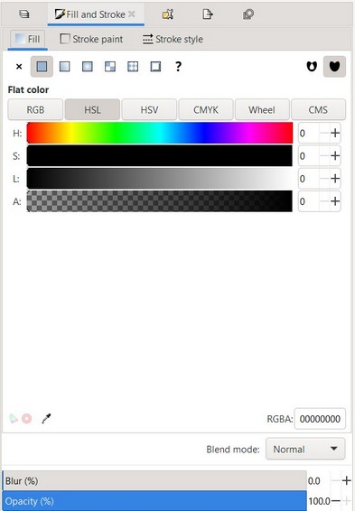
Default rectangles come up with a white fill and a black stroke (outline), and fully opaque. - You will see eight arrow-shaped handles appear around the object. Now you can:
Move the object by dragging it. (Press to restrict movement to horizontal and vertical.)
Scale the object by dragging any handle. (Press to preserve the original height/width ratio.) - Whenever you select an object, the color picker is updated to display its current fill and stroke (for multiple selected objects, the dialog shows their average color).
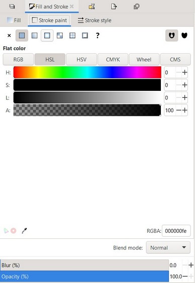
- Using the Stroke paint tab, you can remove the stroke (outline) of the object, or assign any color or transparency to it:
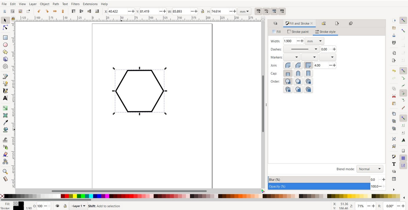
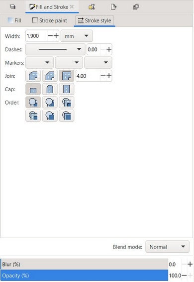
- The last tab, Stroke style, lets you set the width and other parameters of the stroke:
- Instead of a flat color, you can use gradients for fills and/or strokes:
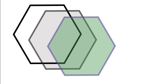
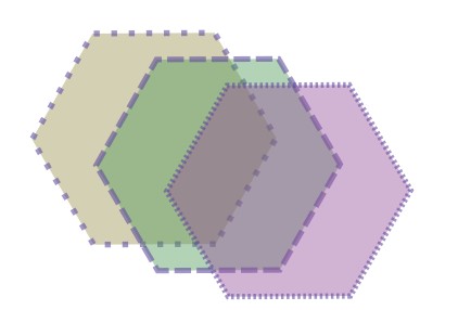
- BOOLEAN UNION: Keeps the common outline of all selected paths.
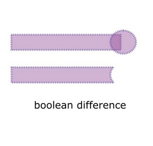
- BOOLEAN DIFFERENCE: Subtracts one path from another one.
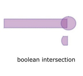
- BOOLEAN INTERSECTION: Only keeps those parts that are covered by all selected paths.
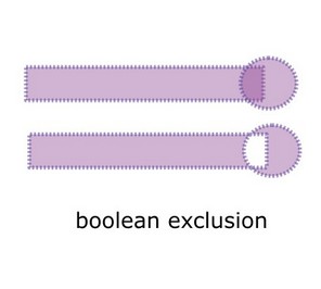
- BOOLEAN EXCLUSION: Keeps those parts which are covered by an odd number of paths (if you have two objects, this is where the objects do not overlap).
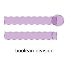
- BOOLEAN DIVISION: The path below is cut into pieces by the path above.
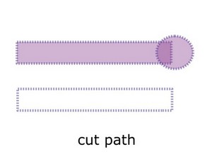
- BOOLEAN CUTPATH: Creates as many paths as there are path intersections between the two paths.
BOOLEAN OPERATIONS
The stacking order of the object matters, so check that the bottom object is the one you want to apply the operation to. All the operations can be found under PATH.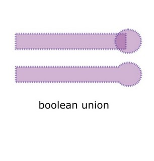
Understanding these operations helped with 3D modelling as well.
3D CAD
I used Rhino because it is easy to model 2D and 3D designs. I also needed Grasshopper to simulate my final project ideas.
Rhino can be downloaded from here.
Rhino tutorials are easily available online, some of them can be found here.
The plugins I used can be found here.
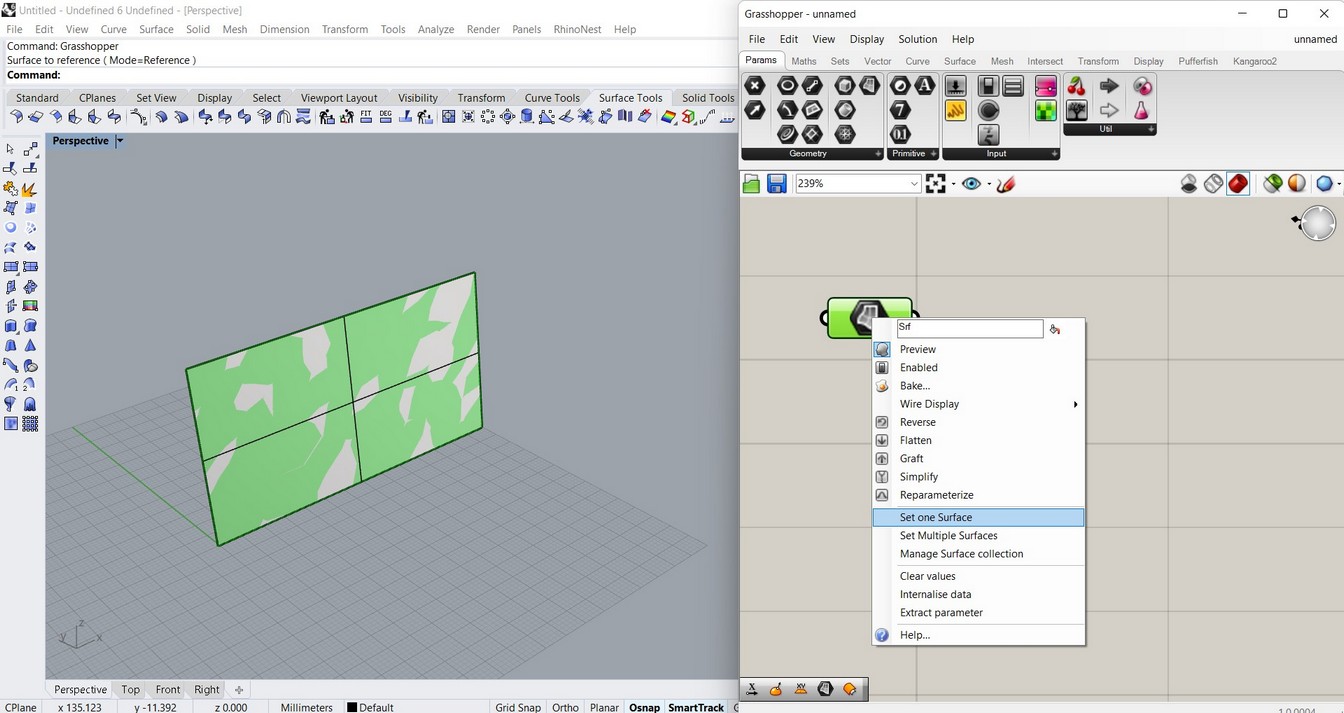
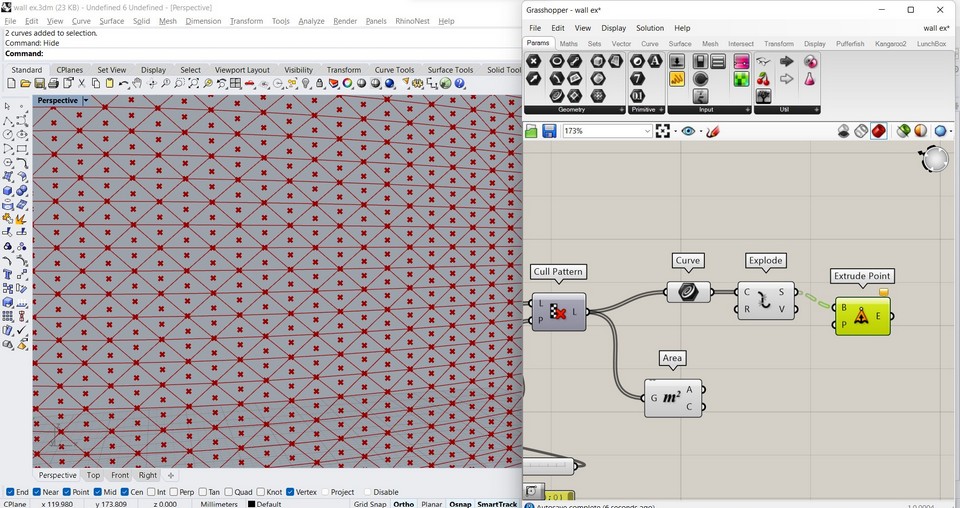
- Create a surface on Rhino and set it to a surface component on Grasshopper.
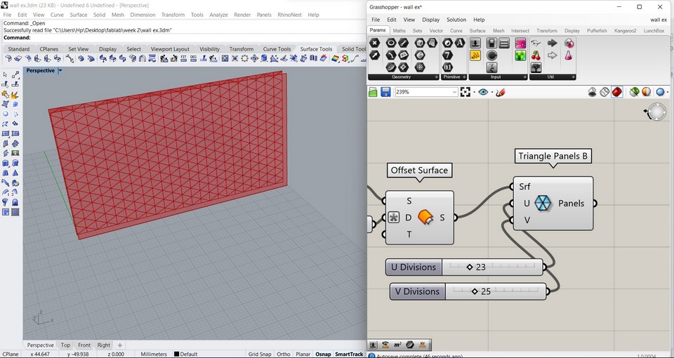
- Use Offset surface to create a thickness and use Triangle panels B to create a pattern and U and V to control the number of components in X and Y direction.
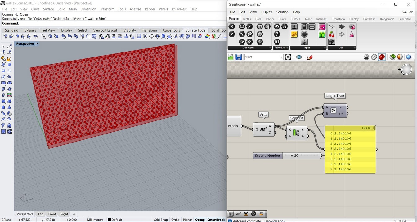
- Use Larger than to find the triangles with area larger than the number slider input.
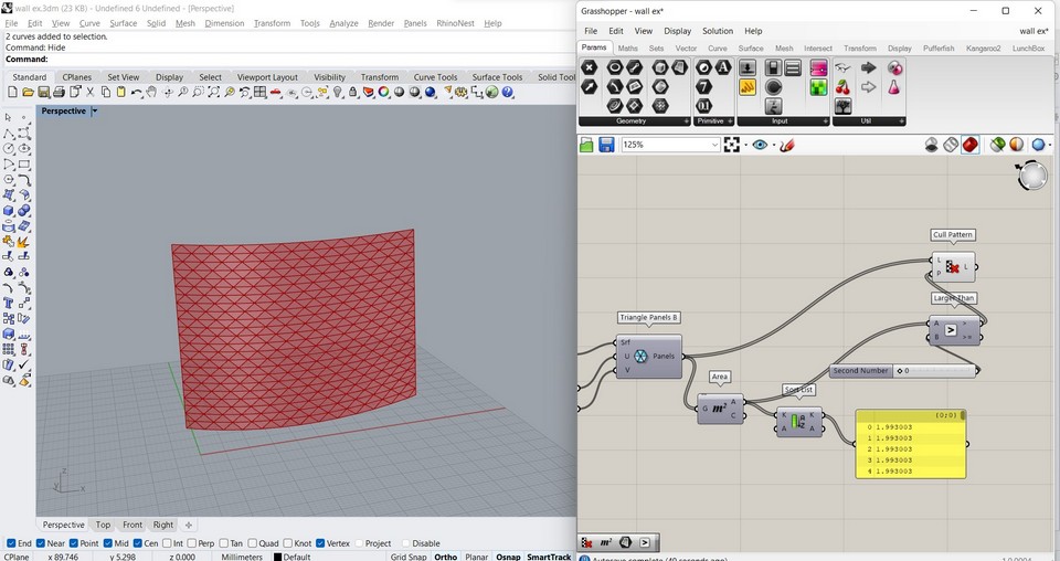
- Cull pattern can be used to introduce a rhythm in the pattern generated.
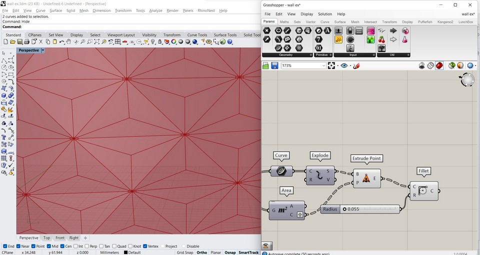
- To create 3 panels for each triangle, use area to extract the center of each triangle and Extrude point
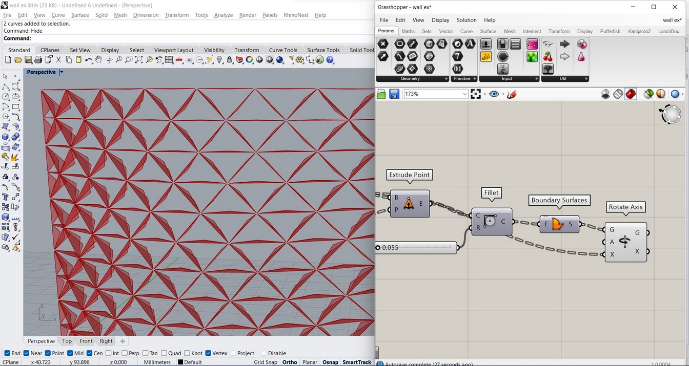
- Fillet creates a gap in the center where the joint would be located.
- Use Boundary surface to make each panel rotate along the axis extracted with Extrude point component.
ANIMATION
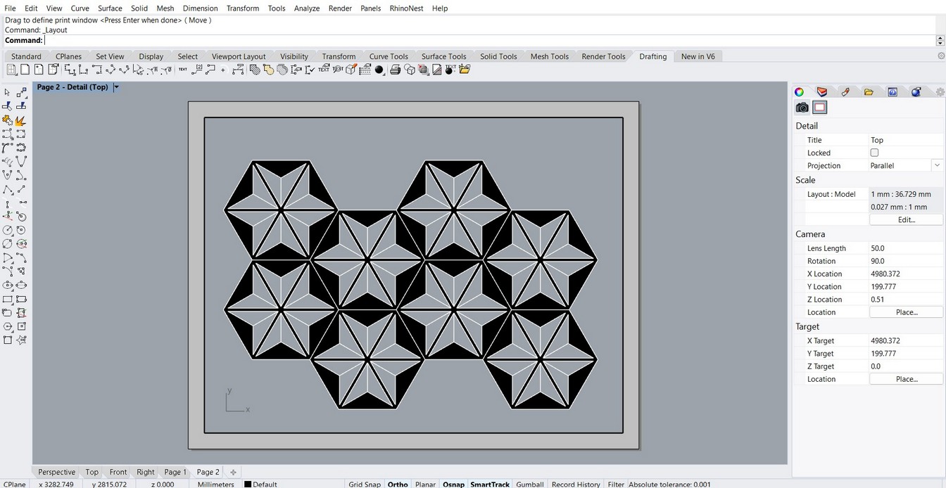
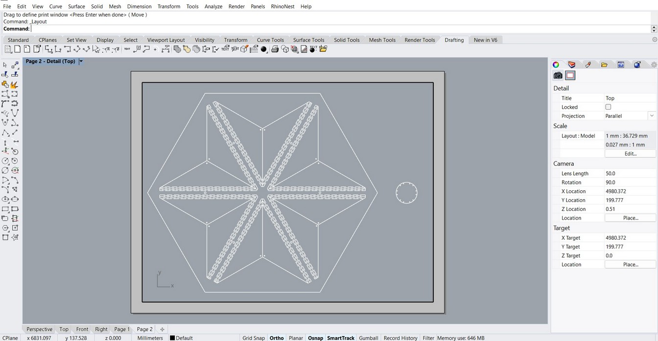
I also drafted one of the modules, so I can text the mechanism later on.
Design files download
Inkscape file
Rhino file
Grasshopper file